
This post was originally published at Walking the Wires
If you are a regular visitor to this blog, you may have heard us mention the DQMH (Delacor Queued Message Handler) from time to time. The DQMH is a framework that we use with our customers, and it is available on the LabVIEW Tools Network.
In this post I’m going to be looking at a particular implementation pattern using the DQMH, although it is just as applicable to any other flavour of QMH, such as the templates that ship with LabVIEW.
We are going to implement a Hardware Abstraction Layer (HAL) in my DQMH module. We are also going to take a look at calling this DQMH module from TestStand, as we think this makes using TestStand a breeze, especially with LVOOP (LabVIEW Object Oriented Programming) abstraction layers.
If you are impatient and want to see what we will be looking at, or if you are time bound and need to get the facts quickly then take a look at the video below. It gives an overview and will hopefully encourage you to keep reading.
The hardware abstraction layer we will be using abstracts the behavior of the ubiquitous bench top DC power supply.
The steps involved are:
- Defining the DC Power Supply API methods
- Create Power Supply parent class
- Implement a descendant class for a specific Power Supply model
- Use Factory Pattern to load a specific class at runtime
- Create Power Supply DQMH module
- Implement DQMH events
- Call Power Supply DQMH Public API from TestStand
1. Define the DC Power Supply API methods
The first part of this task is to define the API methods for our DC Power Supply. In other words, the things we are likely to want to do with it. Fortunately this is a fairly simple instrument so it has limited functionality, which will hopefully make a good demo for this blog post!
The things we are likely to want to do with our DC Power Supply are:
- Set Current Limit
- Set Voltage Level
- Set Output State
- Measure Current Draw
- Reset Instrument
We are likely to want to do these things regardless of the model of power supply in use, although the commands to make them do it may vary considerably.
2. Create Power Supply parent class
We start by creating a parent class to define these methods. This looks something likes this:
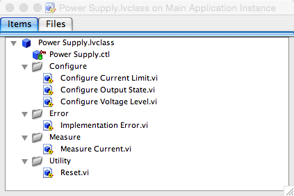
Power Supply Parent Class
Each of the method VIs in the image above is effectively empty, because we do not implement any instrument commands in this class (although we will put something there, but more on that later).
Even though these methods are empty, we use them in the calling code. At run time, the magic of dynamic dispatch calls an override of each particular method, depending on the actual device selected. The child class being called is determined dynamically either through a configuration file or a user selection control.
You can provide a nicer experience (and reduce the risk of bugs) for the developers in your team by setting the option (in the class properties) to require descendant classes to override the parent implementation. Setting this option results in a broken arrow if they don’t provide an override, which will quickly make them realise they missed creating the VI in the child class.
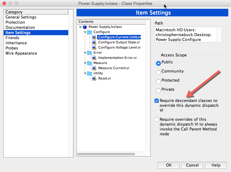
Require descendant class to override method. To open this window, right-click on the parent class on the project and select Properties.
This is all that we need to do at edit time, but what happens if we just call the parent’s method at run time? Is this not just the same as calling a series of empty method VIs?
To make sure we capture this behaviour as an error, we can place an Error Ring inside a wrapper VI and call this VI in each method VI that should be overridden (and therefore never called). We can also define a custom error code and give it a custom error description.
With this method, we see an error if the parent is inadvertently called, as opposed to not having anything happen.
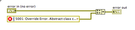
Error Ring with custom error to inform developer that a parent method was called by mistake.
The class private data will typically contain data relating to the instrument (such as VISA refnum) or configuration of the measurements to be performed using the instrument.
In this example, the class private data contains the VISA refnum and the class has accessors for reading and writing this data.

Class Private Data Accessors
3. Implement a descendant class for a specific Power Supply model
The next step is to implement a descendant class for a specific model of Power Supply. Let’s call this class “Agilent 3634A”, and change its inheritance properties to inherit from the abstract Power Supply class.

Inheritance. To open this window, right-click on the parent class on the project and select Properties.
The next step is to create the overrides for this new class.

Create New Override. To open this window, right click the new class and select New VI for Override.
Once we have created the overrides, the Agilent 3634A class should look something like this:
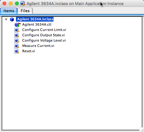
Overrides in Agilent 3634A Class
We can also add some virtual folders to organise our Agilent 3634A class in a similar fashion to its parent.

Organise as parent
4. Use Factory Pattern to load a specific class at runtime
We can now write higher level code, making calls to the abstract Power Supply class and then dispatching the desired specific implementation at runtime.
The Factory Pattern is a means of loading a specific class at runtime by knowing the path to the class definition on disk.
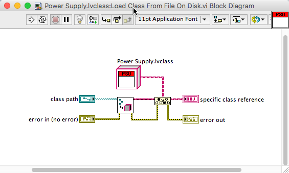
Factory Pattern loads class from path on disk
The great thing about this pattern is that we can add additional child classes in the future without having to make changes to the calling code. In the test world, where new models of equipment become available every few years, this is a powerful feature.
5. Create Power Supply DQMH module
The next step is to create the Power Supply DQMH module. This will be an asynchronously-running module that can receive messages from other modules or from TestStand (which is our use case).
To add a new DQMH module, use the built-in scripting tools that ship with the DQMH Toolkit. Simply click Tools > Delacor > DQMH > Add New DQMH Module.
https://youtu.be/-SXW6lYa6Hs
A test system may have more than one power supply, so we want this to be a ‘cloneable’ DQMH module.
Our project should look like this:
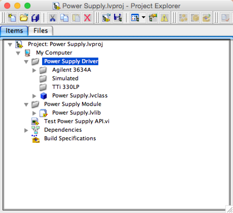
Project including DQMH module and Power Supply classes
6. Implement DQMH events
The final piece is to implement methods in the DQMH module that can be invoked via events.
As we covered earlier, the methods supported are:
- Set Current Limit
- Set Voltage Level
- Set Output State
- Measure Current Draw
- Reset Instrument
In addition to these, one additional method defines the specific power supply being used.
To implement a message that sets the power supply type, we add the Power Supply object to the DQMH module’s private data.

Module private data persisted in Shift Register
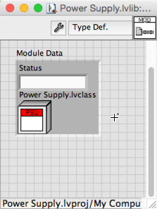
Module Private Data
We can now create a message to define the target power supply class. We already have our Factory Pattern code that loads a class from a path on disk, so our “Set Power Supply Type” message should have a “path” type argument.
The following video shows just how easy it is to create a new message for a DQMH module;
https://youtu.be/xsF0QmGog-g
We can now call our code for loading a class from disk using the path sent as part of the above message. Next we can write the class to the private data of the module. From now on, we know the class of power supply being used and can use this to make calls to the other class methods.

Populate Private Data
To implement the “Set Current Limit Method” we first need to create a new event to send to our Power Supply DQMH module. Since we need the module to set a parameter, we need to create a request type event. The current limit parameter is a numeric value, so we will pass a numeric argument along with our event.
Click Tools > Delacor > DQMH > Add DQMH Event

Create the Set Current Limit Event
We can now add a call to Power Supply.lvclass:Configure Current Limit.vi to the Set Current Limit case of the message handling loop in the power supply DQMH module. At runtime, a child implementation of this method may be called, depending on the configured power supply class type.

Set Current Limit
We can implement the remaining power supply API methods in a similar fashion. This gives us a complete public API for our Power Supply module.
We will have the following request events (request events are things that the outside world can request a module to do):
- Set Current Limit
- Set Voltage Level
- Set Output State
- Reset Instrument
In addition, we will have at least one request and wait on reply event (this is a request event with a reply payload) for the following method:
- Measure Current
We can now launch our module and fire request events on it from LabVIEW or TestStand:
From LabVIEW we can simply drop the Public API methods of the module onto a new block diagram in order to interact with it.
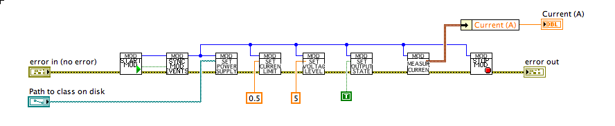
LabVIEW code calling Power Supply DQMH API
7. Call Power Supply DQMH Public API from TestStand
From TestStand, we make calls to the same Public API methods directly form our sequence file. No additional references or operations are required:

TestStand calling Power Supply DQMH Public API
Of course, now that we are using the module from TestStand, we have access to the great features it offers, such as User Management, Report Generation, Database Logging and much more.
The nice thing about this development pattern is that you can develop and debug your module entirely from LabVIEW before calling it from TestStand. You can also use the API testers that are included with each DQMH module as sniffers to check or set values and behaviours in the module event since it is also being controlled by TestStand in parallel. We will go into more details in a future post (In the mean time, we can tell you that for the tester to work as a sniffer, you need to make sure to set the tester to run in the main LabVIEW application instance).
We think that this pattern is a great way for LabVIEW development teams to transition to TestStand. It is also great way for TestStand developers to gain the benefits of dynamic dispatch, which is great for hardware abstraction without needing to deal with LabVIEW objects in TestStand.
If you are going to be running the TestStand example that is included in the example code with this blog post, please make sure to edit the Configuration.txt file to reflect the location of the power supply driver on your PC! You can get the example code as a ZIP file.
As always, we look forward to hearing your thoughts, and if you have a better way, we would love to hear about it, too.
Happy wiring folks!
Chris
Chris, is there any reason why the second two videos are unlisted? The first one is searchable, but I could only get to the other two from this blog post. No biggie, just thought I’d make y’all aware… Incredible content BTW!! Excellent job. Love it. -drew
Hey Drew,
Thanks for the feedback, thrilled that you enjoyed the post. Regarding the videos. I did add them to a playlist on our YouTube Channel however I was worried that people would only find these “short” videos rather than the longer DQMH instructional videos that go into more detail, these are listed on the Channel. Thanks for the comment though, maybe this strategy is confusing and all should be listed in future. Chris
Ah, makes sense when you explain it… Thanks Chris. -drew
Chris, great material. Thanks for taking the time for putting it together and sharing.
Ernesto
Hi Ernesto
Glad you enjoyed it !
Chris
Excellent explanation Chris! Thanks for taking the time to put it all together in such clear terms. I now have a much better idea of how the pieces should work together for a HAL we’re thinking about building.
-Dino
Thanks Chris:
Thanks for the great example.
Any chance you can export the example code as LV2014 version and email it to me?
Thanks again
Allen,
Firstly thanks for following the blog, it’s great to know we have followers and people find the content useful. I’d be happy to back save the demo for 2014 and provide it. I’ve also reached out to you via email to check you have the DQMH Toolkit installed.
Happy wiring
Chris
Thank you very much. This demo is excellent. It is really helping me understand several very important topics including hardware abstraction. (D)QMH cross-module communications and module cloning.
Nice work!
-Allen
The HAL is a standard pattern and I understand its use. Can you explain the benefit of wrapping it in a DQMH? Why can’t I just call the HAL VIs?
Michael,
So one example use case that we’ve had success with is calling the DQMH from Teststand. By wrapping the HAL in a DQMH module the Teststand sequence only needs to care about calling the Public API of the DQMH module. The dispatching of appropriate child classes is all taken care of inside the DQMH module. So, no passing of LabVIEW objects, VISA refnums or any other refnum between LabVIEW and Teststand and no persisting of any of those things in Teststand Globals or Locals.
This also brings the API Tester into play. Because we’re using User Events as the primary message transport, we can interact with our DQMH module from its’ tester in parallel to calling it from Teststand, it’s a great way to perform fault insertion or “sniff” data coming back out of the module. The only caveat is ensuring that the API Tester is running in the Main Application Instance.
I like Teststand but it’s nice to be able to debug my module and its API entirely in LabVIEW and then call exactly the same public API from Teststand without worrying about objects and references in my sequence.
Finally, not everyone is 100% comfortable with LVOOP, they might be happy to create the basic HAL but may be uncertain how to go about calling that from a higher level app or test sequence.
Chris
Thanks i’ve looked at HAL code. Looked at DQMH videos. Trying to get get my head round both. You’ve explained how to do both nicely. Thanks
Question: can you run the clones simultaneously. Because I would like to say run Visa(s) and daq(s) hardware continuously and log data at the same time?
Hi there,
Thanks for taking the time to watch the DQMH videos and for evaluating the HAL example code, we’re glad that you found the material accessible.
To answer your question, yes you can indeed run clones simultaneously, that is the intention in the design of cloneable form of the DQMH. The example use case I always give is based around the common DC Power Supply as most LabVIEW developers have interfaced to one of these at some point in their career. So typically we would physically connect to such an instrument via GPIB, RS232 or LAN. In terms of software we would typically have a VISA reference to that particular power supply. Returning to our DQMH module, we would hold the VISA refnum in the private data of the module (persisted using the shift register in the message handling loop of the DQMH Main VI) and would populate that private data by providing a public API method (Request event) called “Set VISA Address” (or similar). This method would take a VISA refnum provided by the calling code and would write it to the module private data. If we now launch a second instance of this cloneable module we can call the Set VISA Address for both modules, providing a different VISA refnum to each. We now have multiple DC Power Supply modules running which are communicating with different physical hardware using separate VISA refnums.
Perhaps you could provide some more details on your intended use case. Do you require varying rates of acquisition and data generation ? Do you have both input and output from the same physical device ?
Best Regards,
Chris
Hi Chris thanks.
Been doing a lot of RS232/485, Daq analogue inputs/output into projects. Can have 4 parallel loops plus data logging, tdms. All continuous flow.
In some of the rs232, data rate will be 2/sec for Scales & temperature meters. Analogue pressure, flow rates etc, what rate is required.
If you use the cloned modules. Can you have a mixture of rs232/485 & Daq. Or will you have to keep them separate. Going to try HAL method first.
regards
Douglas
Douglas,
I would tend to break that problem down and think of the various processes in your system. It sounds like you have some logging going on. Now, dependent on performance requirements I would consider implementing a logging DQMH module. It possibly would have public methods such as “Set Log File Destination Directory”, “Write Data Point(s) to Log File” for example. Your top level application would be responsible for launching this module however once running, any other module wishing to write something to the log file could call the “Write Data Point” method. The parameters for this method might be (Data, Acquisition Timestamp, Channel Name)
Another module could be the Data Acquisition module. This module would make calls to the Logging module whenever it needs to log something. This method then makes the Data Acquisition module agnostic of a particular log file format. Any changes to the way you log data, file formats etc are contained to just the logging module.
The Data Acquisition module could hold a reference to the I/O resource in the private data cluster of the Message Handler loop (the bottom loop). Just edit the typedef and add an Visa refnum for example. Some typical methods for this module would be “Set I/O reference” (where you would specify the comm port for example) and “Acquire Data point”. If you implement a HAL then you probably have a hardware class in the private data. So another method might be “Specify Hardware Class” where you would select the specific hardware implementation required. If this was a cloned module you could launch several instances of the module and each one could be assigned a specific comm port and it’s own specific hardware class.
I hope this response answers some questions and maybe gives you a few ideas too.
Chris
Chris
Thanks for your help. I have a few simple projects, on the horizon. One data with logging. So will sit down and apply what you’ve suggested.
Many thanks
Douglas
Hello Chris,
Thanks for the great example. I am able to run simple sequential test by managing 3 Power Supplies, 2 Electronic Loads, and DAQmx.
Could you post version from:
CLA E 2016 Chris Roebuck Complementary Architectures LV and TS
It looks more advanced than version from original post.
Thanks,
Sergiy
Hi Chris,
Question on the factory pattern and when you set the class. You set the com port before you set the specific class.
So in the “Set Power Supply Class” you actually replace the original class with the new child class, so the child does not have a com port set.
Is there a nice way to “merge” the original class and the new child class, so in this case the com port you set earlier could be maintained and given to the new child class? Basically any parent data could be transferred over to the new child? Not sure I would want to do that either, just trying to get a better idea of how to use the factory pattern but also force its creation as expected.
Thanks,
Evan
Hi Evan,
I see in the code that the Power Supply DQMH Main VI does have the “Set VISA Resource” listed before the “Set Power Supply Class”, however the instructions in the Test Power Supply API.vi say that the class is selected on step 4 and the VISA Resource name is set on step 5.
Is the order of the cases in the Message Handling Loop what gave you the impression that the port was set before calling the factory pattern? Let me know, so I can correct it.
In general, when using the factory pattern, you want the selection of the class to be the very first step. This is where your object gets created. In other programming languages, this would be your constructor.
That said, if for whatever reason you need to set some values before calling the factory pattern, you would need to make the original object (the one that got the COM property set) an input to the “Power Supply.lvclass:Load Class From File On Disk.vi” and after loading the class and converting “To More Specific Class” make sure that you get the data that needs to be preserved from the original object into the new object.
Thanks,
Fab
Hi Fab,
I appreciate you trust me to have read the whole document first, I pulled the student approach and watched the video. This is what I get for rushing.
This example is great and really opened my thinking to some more approaches with the DQMH. So what I saw is really minor to an example, I was more excited to see if there was a way to use the factory pattern idea to “swap” classes.
Anyway, around 6:15 in the com is set first. Similarly the class type is swapped on the fly. So the old settings and data are “lost”. It is really that example that I saw, but the actual usage of the modules and the document are clear.
But from your comment and reading and thinking through it I can see how to use the pattern and then the DQMH with classes. I am not sure there is a great usage for having a swap class type on the fly, but I felt like I had seen it once.
Anyway thanks for the reply and awesome example.
Hi Evan,
Good catch! This code is all simulated, if we would have been using an actual instrument, we would have found out of our errors!
I will look into editing the video and I will push a new version of the code that has the MHL cases on the right order. I see that the Tester does have the steps described correctly.
Regarding the swapping objects, it is possible, but you would have to provide the code that takes the private data of an incoming object and feeds it into the new object. I have done that in the past, let us know if you would like us to give an example of that or if the description is enough for you to take it from here.
Thanks for reading,
Fab
Hi Fabiola,
It would be great to redo example with the latest DQMH version.
Especially Teststand portion with VISA resources management. And especially with more than one the same kind power supply, e. g. the same Instrument Driver and different Visa resources.
Thanks for the Great Tool,
Sergiy
Hi Sergiy,
Thanks for the suggestion. We have a couple of blog posts planned around this subject, we will keep your suggestions in mind. Glad you like DQMH.
Regards,
Fab
In the demo, it is only DC power, I have DC and AC power supply, do I need two DQMH modules or one ?
If both power supplies will have the same API, then use the same DQMH module. If you plan to use the front panel of the DQMH, another way to make this decision is to determine if you can use the same front panel for both the DC and the AC power supply.
I suspect that the API (DQMH Request and Broadcast events) will be different for both power supplies and you should have a different module for each.
Thanks for your reply.
You mean it is better to make two DQMH module for AC and DC power supply?
And for each module, I can use same oop API.
The API includes:
Set Current Limit, Set Voltage Level, Set Output State, Measure Current Draw, Reset Instrument
If your AC Power supply will have only the above methods and no more, no less, then you can use the same DQMH for both types of Power Supply.
DQMH Module may be very universal. For example I use one module (PwrSupply ElLoad) to control 3 DC Power Supply and 2 Electronic Loads. It is possible to do some little cheating (“Set Output State” will call “Enable Output” for Power Supply, and “Enable Input” for Electronic Load). But AC and DC Power Supplies are very different if you need to read Amplitude, RMS value for AC. So, maybe two modules is better idea.
Which one you are using, and what do you need to do with power supplies?
Regards, Sergiy
This is a great presentation and brings a lot of stuff together that is very important (for the work I do) and not covered a lot in most other DQMH tutorials and presentations. It would be really great to see this in use with an actual instrument; bringing in instrument addresses from files; initializing the instrument in a useful setting, sending back data, etc. I think without an actual instrument in place, a lot of important points can’t be meaningfully explored and presented. Yes, most of us wouldn’t have the instrument selected but that would make the code extra-instructive as then we could implement modifications for our actual instrument and top-level presentation architecture.
Hi Carlos,
Check out the post by Michael Howard that has an example using an instrument:
https://dqmh.org/simplifying-your-hardware-abstraction-layer-hal-with-lvoop-and-dqmh-part-1/
If you have more questions, please feel free to post them on the NI forum at
https://forums.ni.com/t5/DQMH-Consortium-Toolkits
Thanks for your trust on DQMH,
Fab
Very helpful! Thanks for sharing!